Groundwater Exploration Techniques
Groundwater Exploration
Groundwater conditions at a particular location can be described through its distribution of permeable layers: Such as sand, fractured rocks, and gravel, and impermeable layers, which are zones of low permeability such as clay, till, and solid rock.


Image: Courtesy
A contrast between the petrophysical properties of formations will give us a geophysical picture of these subsurface structures. The mostly used petrophysical properties are:
- Seismic velocities: They are related to elastic properties & density. They define the speed with which various elastic deformations propagate through the materials.
- Electrical conductivity: describes how easily electric current can flow through a medium when subjected to an applied electric field.
- Dielectric constant: This is a measure of the ability of a material to store electric energy.
Electrical conductivity within rocks
Within rocks and other materials, there are free electrical charges. When an electric field is applied to a material, these charges experience an electrical (Coulomb) force. This force causes the free charges to move through the material along the direction of the applied field; with positive charges moving parallel to the field and negative charges moving in the opposite direction. In conductive materials, free charges move quite easily and strong currents may be induced by a relatively weak electrical field.
In contrast, resistive materials require strong electrical fields to produce any significant current. Resistivity, an equivalent physical property to conductivity is resistivity. By definition, the resistivity of a material is the reciprocal of its conductivity.

Image credit: Courtesy
Conductivity of common rocks
Most rocks contain pore spaces which are at least partially saturated with ionic fluids. These fluids include freshwater, brackish water, ocean water and brine. Because pore fluids have a higher conductivity than most rock-forming minerals, electrical current generally prefers to flow through the pore space whenever possible. Air is a poor conductor therefore unconsolidated dry sediments have a high resistivity.
NOTE: Current flows through a rock’s pore-fluid via ionic conduction. As a result, the bulk conductivity of the rock depends significantly upon its:
- Porosity.
- Fluid saturation.
- The type of fluid contained within the pore space

Image credit: Courtesy
Till is a mixture of sand, clay, and partly chalk with a wide variety of grain size distributions. The clay content influences the hydraulic conductivity significantly. Clay and till have low hydraulic conductivities. They form hydraulic boundaries dividing aquifers. Till is unsorted and unstratified drift, generally over-consolidated, deposited directly by and underneath a glacier without subsequent reworking by water from the glacier. Clay is a type of fine-grained natural soil material containing clay minerals. Clayey materials have low electrical resistivities (5 – 60 ohms).
- They form hydraulic boundaries dividing aquifers.
- They are often a target in electrical or electromagnetic surveys.
- Tills and clays prevent contamination of aquifers from the surface.
Hydraulic Conductivity Values for Earth Materials
A gravel whose pores are filled with sand, silt and clay will have a lower hydraulic conductivity than an open framework gravel found in a river bar because the former’s pores are not as interconnected as the latter. Materials whose pores are interconnected and large have higher hydraulic conductivity values.

Ranges of intrinsic permeability, k, and hydraulic conductivity, K, values. The alternating colours are used to make the chart easier to read. For conversion purposes, 1 cm/s = 1.02 × 10⁻⁵ cm2 and 1.04 × 1000 Darcy (after Freeze and Cherry, 1979).
Geophysics
This is the study of the physical responses of rocks under passive or active perturbation/disturbance, and the data interpreted to infer geology. Applied geophysics blends physics principles with Earth sciences to explore and understand the Earth's subsurface for practical applications. Geophysics enables us to understand the variations in the petrophysical properties of the subsurface formation. Through this, we can tell the location of different mineral deposits and other resources beneath the Earth’s surface.
Groundwater Exploration Techniques
Most of the liquid freshwater resources are stored underground as groundwater. There is however a variability regionally in terms of distribution on Earth. This variability is influenced by climatic conditions as well as the subsurface geology. Only a detailed knowledge of groundwater will lead to sustainable development and utilization. This detailed knowledge is obtained through exploration.
Groundwater exploration therefore not only focuses on sinking new boreholes but aims at understanding the groundwater system as a whole. 
 ---------------------------- equation 1
 ---------------------------- equation 2
where ρ is the internal resistivity of the sample. Provided we know the geometrical quantity (A/δl) we may measure the resistivity using: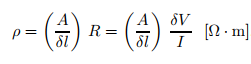 -----------------equation 3
 ------------------------------equation 4
 -----------------------------equation 5where k is the geometrical factor associated with the given array.

For the Wenner array in which the electrodes are simply equi-spaced, apparent resistivity is given by:


Image Credit: Courtesy
What Parameters are of Importance during groundwater exploration
- The spatial extent
- The hydraulic properties of the host rock/aquifer
- The interactions with under and overlying aquifers or surface waters
- The spatial and temporal variations of groundwater properties
- Groundwater recharge
- Natural discharge
- Extraction
- Depth and Age of groundwater
The most commonly used groundwater exploration methods are:
Geoelectric methods: The parameter of interest is the resistivity structure of the underground formation which helps to identify the variations by discriminating between different zones:
- Fresh water and salt water,
- Soft-rock sandy aquifers and clayey material,
- Hard rock porous/fractured aquifers and low-permeable claystone and marlstones,
- Water-bearing fractured rock and the solid host rock.
Resistance and Resistivity of Rocks
Resistance: When we pass a current, I through a sample or through the ground, and measure the resultant voltage drop ∆V, we are actually measuring the total "resistance", R of the rock(s). Resistance is simply obtained from such an experiment using the relation:
---------------------------- equation 1The total resistance, R in a given experiment is a function of geometrical factors and the "resistivity", ρ of the target. The former is only related to the experimental configuration, while the latter is an inherent property of the target (i.e., of the rock). For example, if we use a cylindrical core sample as the target and pass the current along the length of the sample, the total resistance is proportional to the length, δl, and inversely proportional to the cross-sectional area, A so that;
---------------------------- equation 2where ρ is the internal resistivity of the sample. Provided we know the geometrical quantity (A/δl) we may measure the resistivity using:
-----------------equation 3The resistivity may also be defined as the resistance between opposite faces of a unit cube of the target material.
Conductivity: While resistivity measures the resistance to current flow for a unit cube, conductivity is the inverse of this (i.e., the ease of current flow).
Electrode Configurations/Arrays
When resistivity measurements are made from the ground surface, the relationships for resistivity established in equation (3) still hold:
------------------------------equation 4However the (A=δl) geometric terms must be replaced with a geometrical factor (also with the dimensions of length) appropriate for each given electrode configuration.
Field resistivity arrays
A number of different electrode configurations are common in resistivity prospecting. In most cases current is passed between two current electrodes, and
voltage is measured, elsewhere, between two potential electrodes. For all such arrays a resistivity formula exists of the form -----------------------------equation 5NB: The geometrical factor is calculated assuming a simple "homogeneous half-space" model, while in reality the current paths are unpredictable, so that the resistivity calculated in equation (5) is termed "apparent resistivity"
Four types of arrays are pole-dipole, dipole-dipole, wenner, and schlumberger array (current electrode spacing is varied).
Four types of arrays are pole-dipole, dipole-dipole, wenner, and schlumberger array (current electrode spacing is varied).
The Schlumberger array is the most commonly used in groundwater exploration. For this array (Schlumberger) the apparent resistivity is given by:
Image: Courtesy
For the Wenner array in which the electrodes are simply equi-spaced, apparent resistivity is given by:
Image: Courtesy
Types of Resistivity Surveys
Lateral profiling (HEP)
In lateral profiling, the array (or some part of the array) is moved progressively along the line direction, and the apparent resistivity, ρa is monitored as function of position on the line.
Vertical electrical sounding
Depth sounding takes advantage of the change in penetration of the electrode potentials with increasing separation. The wider the electrode separation, the greater is the fraction of the survey current that penetrates into the substratum.
An increased current penetration means that the apparent resistivity will be related more closely to the deeper layers. Thus, the apparent resistivity will change with array spacing: initially, at smaller spacings the apparent resistivity will largely respond to the resistivity of the shallowest layers, and at larger spacings it will respond to the deeper layers. Hence a plot of apparent resistivity against array spacing will give an indication of the trends in resistivity with depth.
Electromagnetic methods: These methods detect the electrical properties of the subsurface by inducing EM energy within the subsurface and measuring the response of earth materials.
The two methods above are most commonly used to explore groundwater conditions because aquifers, aquitards and bedrock often differ in the measured quantity of resistivity or electrical conductivity.
Other methods include:
Seismic methods: use artificially generated seismic waves and their interaction with subsurface materials to create detailed images of the Earth’s interior.
Ground penetrating radar (GPR): radio wave pulses are transmitted at centre frequencies into the ground to study the subsurface
Magnetic resonance sounding: uses the hydrogen proton of water molecules which possess angular momentum and an associated magnetic moment without physically rotating. It is a new technology but has been successfully used for groundwater exploration.
References
Pratt.G. (2005). Applied Geophysics. Department of Geological Sciences and Geological Engineering, Queen’s University
GWB Myanmar Groundwater Project (2019), Interpretation of Geophysical Data to Find Groundwater, retrieved from https://medium.com/gwb-myanmar/using-simpeg-software-to-conduct-geophysical-data-analysis-and-inversion-many-parameters-of-7fd4f873c58d, on 30/03/2024
Kirsch. R. (2006). Groundwater Geophysics A Tool for Hydrogeology (2nd ed.).
Wiederhold et al. (2021), Geophysical methods help to assess potential groundwater extraction sites.

